HOMAT Applications
ICME application: U-O forming of a X65 steel linepipe tube with ferrite-pearlite microstructure
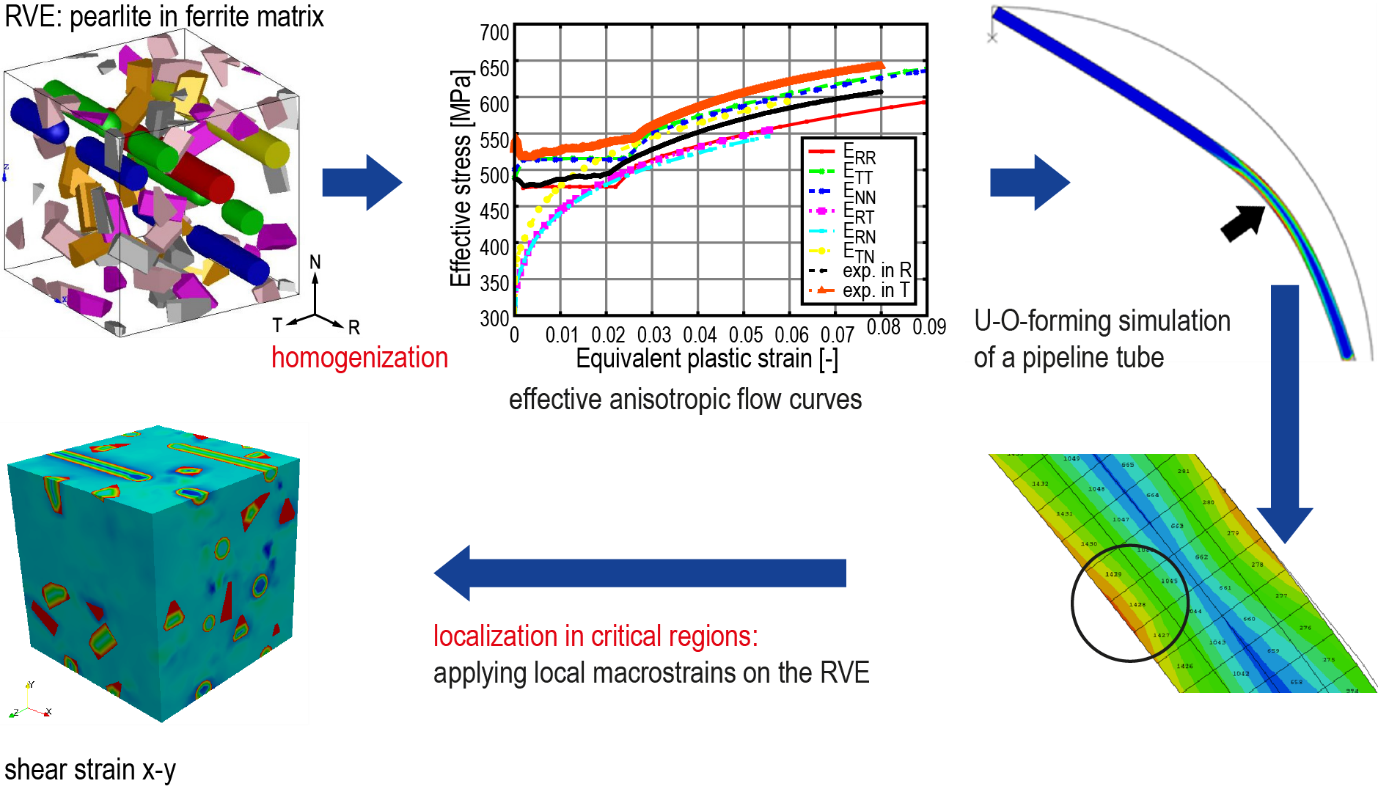
In the ICME (Integrated Computational Materials Engineering) multiscale analysis of the manufacturing process of a component with heterogeneous microstructure, it is essential to be able to bridge the scales both up and down. HOMAT permits such scale bridging steps. At first, in a homogenization step, starting from a detailed description of all material heterogeneities at the lower scale, it performs an upscaling to evaluate the effective material properties. Alternatively, HOMAT performs a localization step to step down to the scale of the real, heterogeneous material microstructure,. In the figure, this multi-scale analysis approach is outlined for the U-O forming production step of an X65 steel linepipe tube having a pearlite-ferrite microstructure. The corresponding effective thermal properties (thermal conductivity, capacity, density) and thermo-elastic properties (Hooke matrix, thermal expansion coefficient, etc.) are evaluated by HOMAT. The effective anisotropic flow curves are generated via virtual tests conducted in Abaqus. These properties are used in the U-O forming simulation of the linepipe tube at the macro-scale. In tube regions identified as critical, macro-strains are extracted from the forming simulation and applied as boundary conditions for the RVE of the ferrite-pearlite microstructure. Finally, the localization analysis permits identification of the critical regions of the microstructure (e.g. grain boundaries) where failure could be initiated.
Austenite to Ferrite Phase Transformation of a Low Carbon Steel
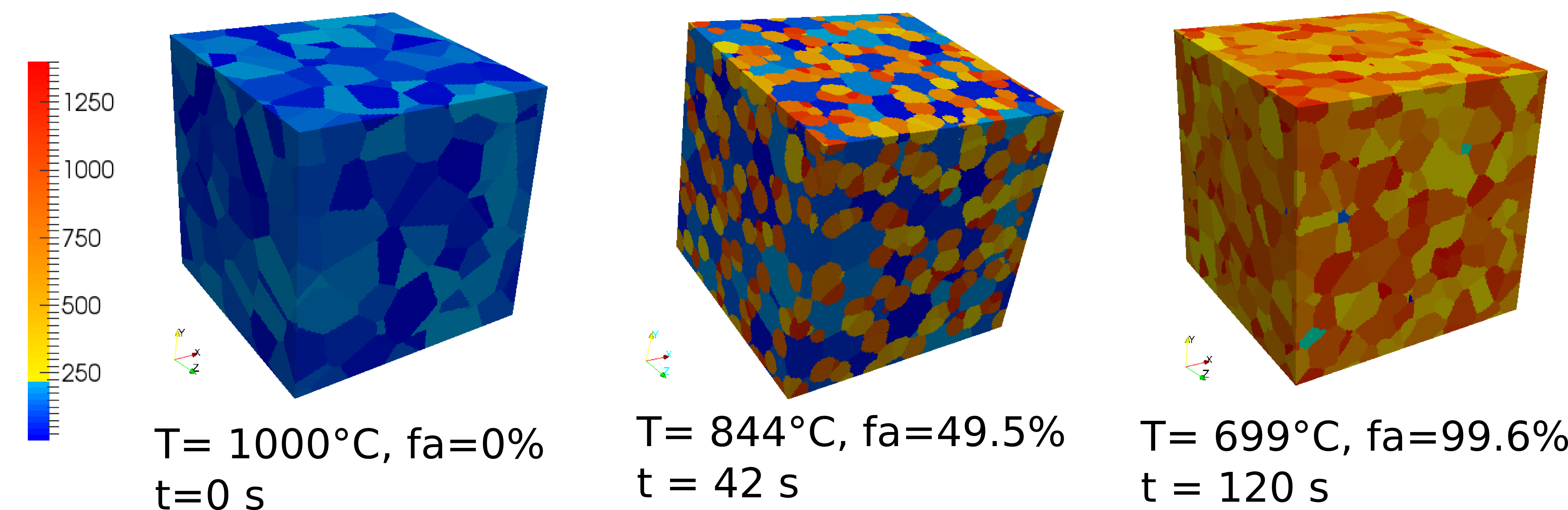
Fig.1 : Phase field simulation of the austenite to ferrite phase transformation during cooling.
A synthetic 3D RVE of the initial austenite microstructure of a Fe-0.023C-0.17Mn-0.009Si [wt %] low carbon steel is generated by Voronoi tessellation within MICRESS®. It contains 213 randomly oriented grains and is discretized by 1543 cells. During cooling, MICRESS simulates the phase transformation kinetics as a C diffusion process. The austenite phase transforms into ferrite without cementite formation but with residual austenite grains over the temperature range shown in Fig. 1.
From the MICRESS® simulation, at selected time steps, the simulated microstructure is extracted as well as the grain orientation file and transferred to HOMAT. Thermoelastic homogenization is then performed. Fig. 2 and 3 illustrate the temperature variation of the effective Young modulus and of the volumetric eigenstrain. Ehom(T) # decreases strongly during phase transformation; whereas the effective eigenstrain increases during this transformation due to larger molar volume of ferrite than austenite. Moreover, a simulated dilatometer curve is generated which can be compared to an experimental one.
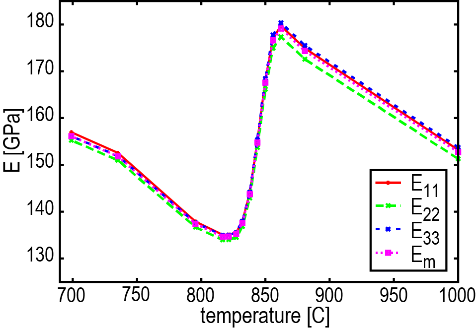
Fig.2 : Temperature variation of the effective Young modulus during the cooling process..
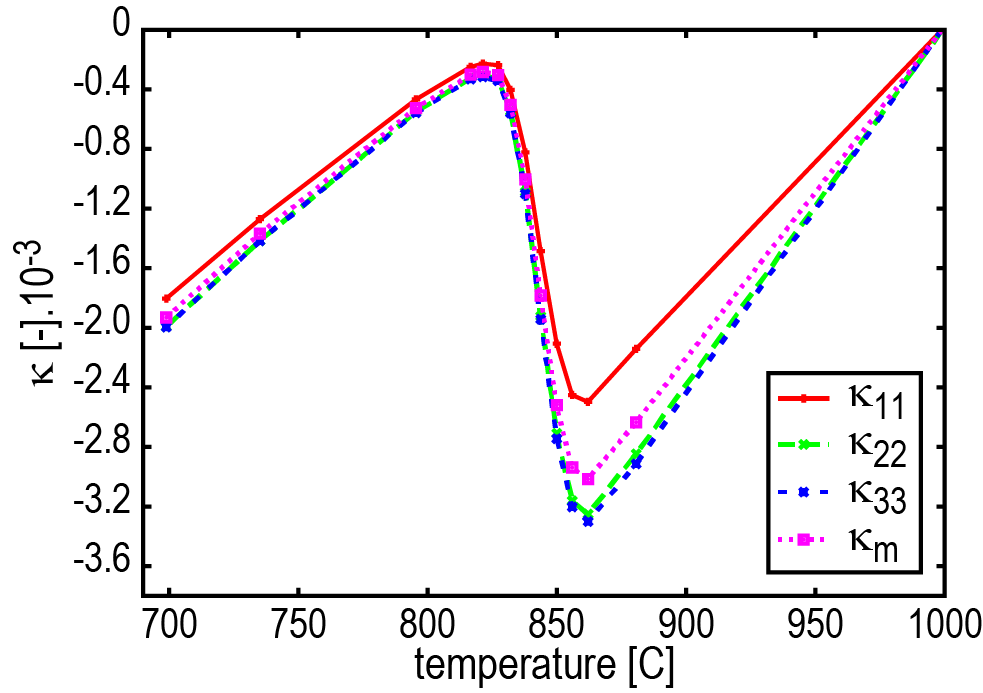
Fig.3: Temperature variation of the volumetric eigenstrain during the cooling process.
Equiaxed and Directional Solidification of a AlSi7Mg03 Alloy
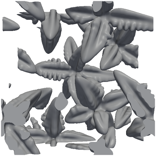
Fig.1 : Evolution of the equiaxed and directional solidified A356 microstructures: primary equiaxed dendrites grow in the bulk during isothermal solidification.
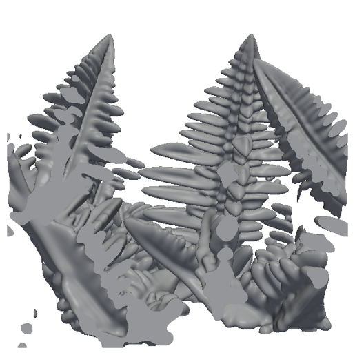
Fig.2 : Directional fcc Al dendrites nucleate at the bottom and grow in the thermal gradient direction during non-isothermal solidification.
From the thermal analysis of the solidification of an axisymmetric A356 bowl in die casting local cooling curves are derived. A volumetric heat extraction rate of -240 J/cm3 is applied on the RVE with and without a thermal gradient of 15 K/mm (from bottom to top), such that the thermal histories at macro- and microscale are consistent. The multicomponent phase field simulation with MICRESS® predicts the primary solidification of six dendritic fcc Al grains, either of equiaxed or directional morphology. Then, at fS ≈ 50% Si eutectic begins to form and at the end of solidifcation small Mg2Si particles occur (see Fig. 1 and 2).
Dendritic microstructures are extracted at selected fraction solids and transferred to HOMAT. Thermal and thermoelastic homogenization runs are performed for both dendritic morphologies. In Fig. 3 and 4 the effective thermal conductivity of the mushy zone during equiaxed and directional solidification is plotted as function of the temperature. Due to undercooling and recalescence phenomena, the relationship between thermal conductivity and temperature is non-unique in the mushy zone; whereas the λ(fS) curves are unique and more suitable for casting simulations. Moreover, the adopted multiscale approach (phase field simulation + homogenization) outperforms experimental measurements as the laser flash method is not able to distinguish the equiaxed from the directional solidification.
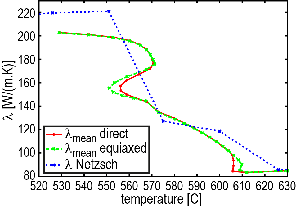
Fig.3 : Effective thermal conductivity of the mushy zone during equiaxed and directional solidification are plotted as function of the temperature (The experimental thermal conductivity measured by laser flash is added).
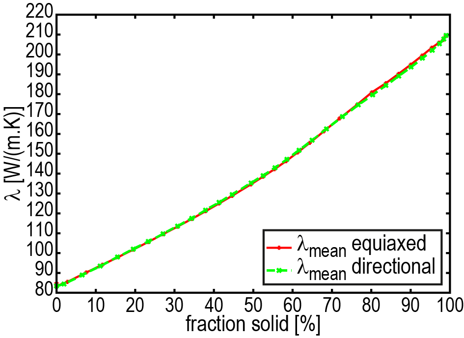
Fig.4: Conductivity as a function of fraction solid
The effective homogenized elastic modulus of the directional morphology as well as the volume averaged elastic modulus are outlined in Fig. 5 as function of fS. HOMAT performs a noticeable correction of the volume averaged value due to large implicit forces (mainly near fS = 50%) generated at the solid-liquid interfaces. In Figure 6, Ehom(T) is plotted non only for the mushy zone but for the whole cooling process as well as an experimental curve [1]. A significant difference is recorded above 300°C, due to the fact that Ehom is purely elastic and contains no viscous effect; whereas the experimental Eexp values contain always viscous effects at high temperatures.
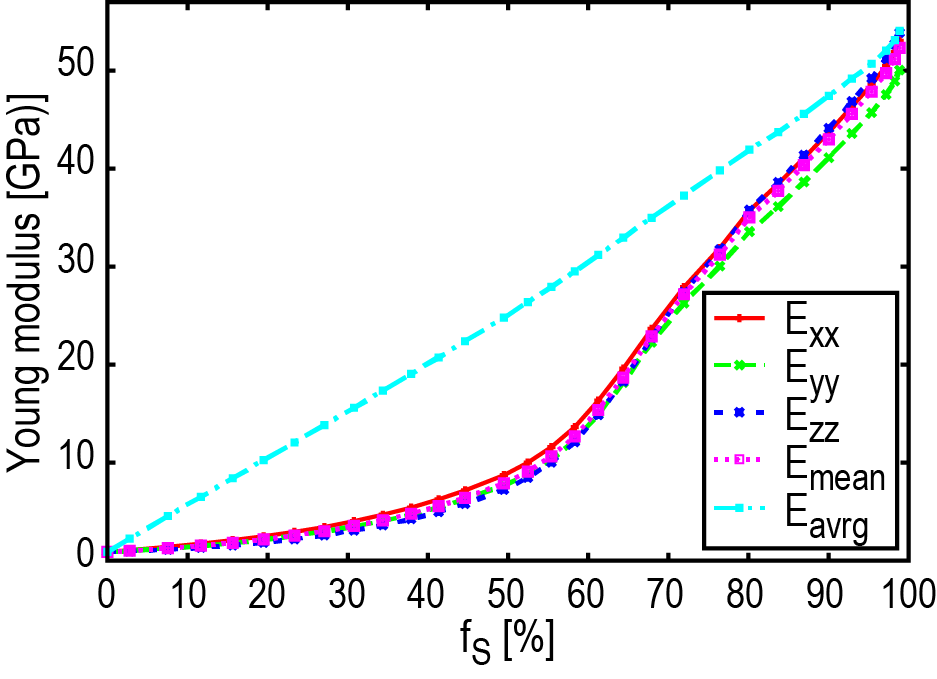
Fig.5 : Effective Young moduli per direction, the mean modulus as well as the volume averaged one of the directional solidified microstructure as function of the fraction solid in the mushy zone
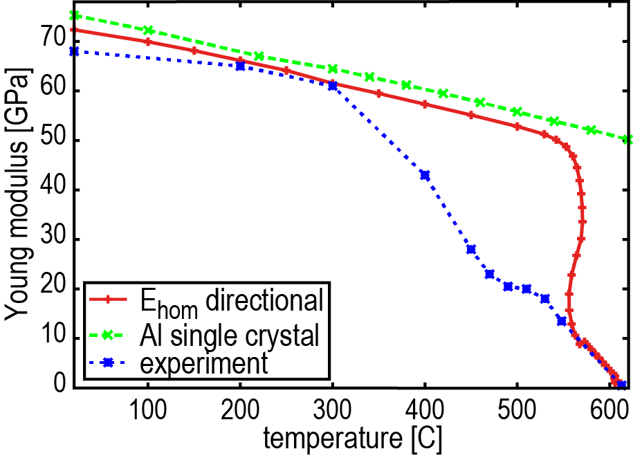
Fig.6: The temperature dependences of the mean Young modulus of the directional microstructure, the experimental one and of the Young modulus of the pure Al single crystal are plotted for the whole cooling regime
Effective elastic properties of an injection moulded polypropylene plate
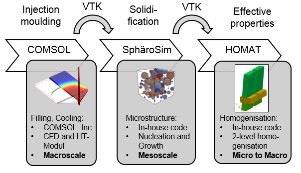
Fig.1 : Multiscale simulation chain in order to predict microstructure dependent effective material properties.
The ICME strategy has also been applied to predict the local variations of elastic properties in semi-crystalline components, for example an isotactic polypropylene staggered plate produced by injection moulding. The multiscale simulation chain developed in order to predict microstructure dependent effective mechanical properties is shown in Fig. 1 and outlined in [1].
In a first analysis at the macro-scale, the flow, the cooling and the solidification behaviour of the polymer melt has been calculated by applying the multiphysics FE program COMSOL®. Then, at microscale, the calculation of the solidification process and of the microstructure evolution is performed by SphaeroSim, a dedicated cellular automata for semi-crystalline solidification, developed at the Plastic Processing Institute of RWTH Aachen University. The calculated final microstructures (see Fig. 2) are then transferred to HOMAT. A dedicated two-level homogenization scheme has been developed to model 3D spherulites, characterized by a quasi-radial distribution of twisted lamellae around a mono-crystal nucleus. Fig. 3 illustrates the complex RVE design skew3D realized to describe the crystalline-amorphous lamella with forward and backward branches due to secondary nucleation.
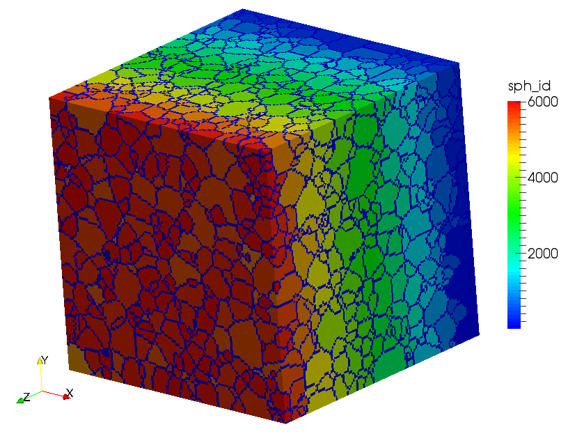
Fig.2 : Spherulite microstructure located at the top skin in the 3 mm section of the staggered α-iPP plate.
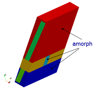
Fig.3: RVE design skew3D with forward and backward branches
The variation of the effective Young modules over the plate sections S2 (=2 mm) and S3 (=3 mm) are outlined in Fig. 4. The 2-level homogenization scheme predicts an orthotropic equivalent behaviour in both sections. Their variation over both plate sections is asymmetric due to different cooling behaviour at the two mould walls and the induced microstructure variations..
Fig.4 : Variation of the effective Young modules over the thickness of sections S2 and S3 predicted with lamella design skew3D
Mono- and multilayer homogenization of effusion cooled multilayer plates
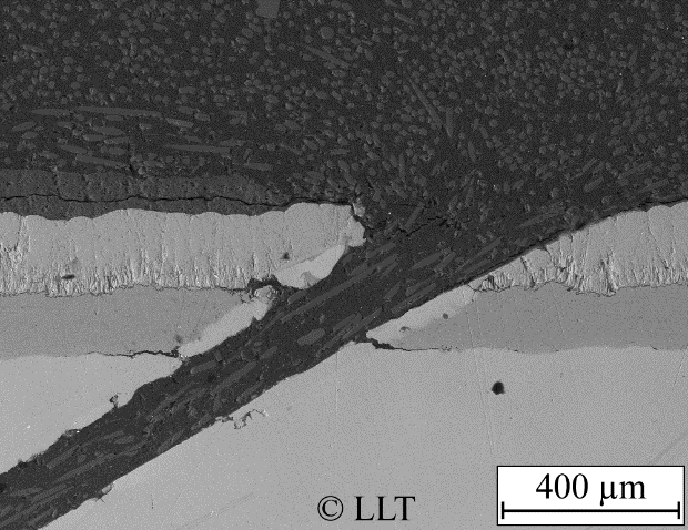
Fig.1 : Laser drilled cooling channels in the multilayer plate.
Fig.2 : RVE of an effusion cooled multilayer plate composed of thermal barrier coating, a bondcoat and a superalloy substrate.
This example shows the versatility of the standalone version of HOMAT. Here the effective elastic properties of a flat effusion cooled multilayer plate, comprised of a superalloy CMSX-4 substrate, an MCrAlY bondcoat and a TBC of Yttrium stabilized Zirconia oxide, are determined. Each unit cell (see Fig. 1 and 2) includes a laser drilled central hole and, at the edges, a quarter of a cooling channel passing through the three layers. The unit cell is inclined by an angle of 30°. Each layer has its own steady state temperature distribution, predicted previously by a conjugate heat and fluid flow analysis [1].
Thermoelastic mono-layer and multi-layer homogenization runs are performed with HOMAT. An orthotropic equivalent stiffness behaviour is predicted for each layer as outlined in Table 1. Due to the local diffusor designed in the TBC layer, its stiffness reduction is more pronounced (ΔEred = -20.3%). The orthotropy of the effective Young modulus can be explained by an analysis of the periodic microscopic displacements on the TBC layer, induced by implicit forces acting at the solid/gas interfaces. In all three directions, the implicit forces act to suppress the presence of cooling channels. The z component is the most significant one, leading to a larger correction of the volume averaged elastic module in the thickness direction. In contrast to the monolayer homogenization, in the multilayer homogenization additional forces at the solid/solid interfaces act in the z direction. These forces tend to extend the bondcoat, the layer with the largest Young modulus, and to compress both other layers. Thus, the z displacement component is reduced in the TBC and substrate, and increased in the bondcoat layer.
| Layer | Ehomx [Mpa] |
Ehomy [MPa] |
Ehomz [MPa] |
Δ Ey,mean | Δ Ered |
| TBC | 39.812 | 35.221 | 39.222 | -7.5% | -20.3% |
| Bondcoat | 155.629 | 139.890 | 158.056 | -7.5% | -16.2% |
| CMSX-4 | 85.530 | 79.418 | 85.923 | -5.0% | -14.1% |
| Multi | 85.886 | 79.472 | 81.829 | -3.6% | - |
Table 1: Effective Young moduli of each mono-layer and of the multilayer. In column 5 the relative difference of Ey to the mean value and in column 6 the relative difference of the mean modulus to the layer modulus without any cooling channel.
Fig.2 : Microscopic displacement components in the TBC layer induced by implicit forces in the same direction.
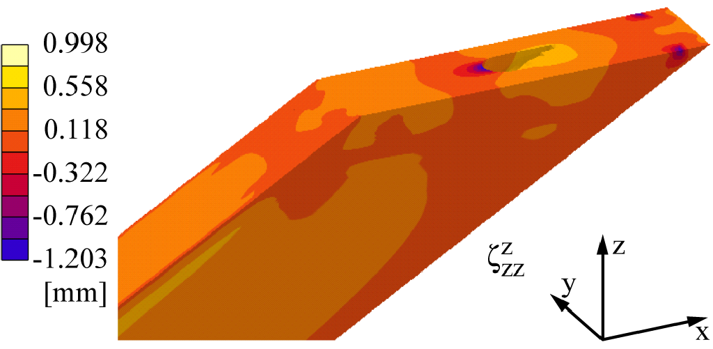
Fig.3: Microscopic displacement in the z direction of the multilayer homogenization of the flat plate